Page Contents
1. Terrain excavation as a project
Each project has its own numeric identifier and name. This identifier also serves to uniquely identify field documentation and digital data.
Each project has its purpose and leader. The plan is usually formulated by the project sponsor (customer), if this is not the case, the project manager defines his partial research plan on behalf of Archeoconsult.
Each project has its own granulation in the form of partial tasks. The partial tasks in a typical case (advance research) are:
- – definition of the project and its intention
- – field part of the project (definition of the method and nature of field data)
- – transfer of data for processing
- – data processing and definition of their content
- – delivery of results to customers (research report)
- – presentation of the project on the web domain
Each subtask has a defined leader who is responsible for the task
2. Terrain excavation and its entities
The field part of the project means field excavation and documentation, completed by submitting field data for further processing. The head of the field event (archaeologist) is responsible for the research process and research data until the data is received at the office.
2.1. Terrain and documentation entities
The essence of archaeological research is the analysis of the archaeologized situation (decomposition of the terrain situation into simple terrain entities) and their documentation in such a way that it is possible to synthesize the data into meaningful gnoseological structures. The field part of the project can be viewed as a list of terrain entities, a list of documentation entities and the relationships among them.
Tab.1: Terrain and documentation entities of field excavation
Terrain entities |
Popis | |
|---|---|---|
| Terrain stratification entities: | finds | artifacts in the terrain situation as a content of deposit. Mostly taken as part of the SU, but the possibility to treat it as a separate record unit (“exceptional finding”) |
| (real entities of physical archaeological record) | stratigraphic unit (SU) | basic analytical unit of stratification according E. Harris. there are three types corresponding to the three types of events: deposit (result of deposition ), cut (removal of deposition) and construction (artificial structure dividing stratigraphic sequence) |
| object | higher category associating SUs according to a defined interpretative key (e.g. oven, rubbish pit etc…) | |
| Arbitrary terrain entities: | excavation polygon | the space in which the excavation and documentation takes place |
| (artificial – dependent on excavator choice) | profile | line presentation of the SU surface |
| cut/section | vertical projection of stratigraphy as a result of cutting an archaeological record | |
| sample | “pars pro toto” of the stratification entity determined for detailed examination |
|
Documentation entities |
||
| lists and forms of evidence | descriptive and record lists, SU forms | |
| drawings | drawings, sketches, photo-sketches | |
| geodetic documentation | spatial fixation of field and documentation entities by the method and aids of geodesy | |
| photo documentation | field photography and photogrammetry |
The difference between field and documentation entities can also be expressed as the relationship between the processing and the result of field research. Documentation entities are usually not presented as a result (printout) of processing data while mostly terrain entities are important. Trenches on Fig. 01, 02 could be accompanied by terrain and documentation entities as well.


Regardless of the specific nature of the research and the presence / absence of traces of activities of historical communities in the monitored area, some field entities and corresponding documentation entities are a mandatory part of the field project. It follows that each field action must have a certain minimum amount of field data. Tab. 2. defines mandatory/obligatory items of terrain research entities, Tab. 03 defines mandatory/obligatory items of documentation entities:
Tab.2.: Mandatory terrain entities.
| Terrain entity | Description |
|---|---|
| Stratigraphic unit (SU) |
Each destructive intervention in the terrain means the removal or partial removal of at least 1 stratigraphic unit, which must therefore be defined. |
| Research polygon (area, trench, …) | Each field activity takes place in a specific place and in an area that is delimited and thus spatially definable. |
Tab.3: Mandatory documentation entities.
| Documentation entity | Description |
|---|---|
| Su description (SU form) | As at least 1 SU is always defined, it must be stated in the descriptive documentation. |
| Geodetic measurement | Regardless of the type of measurement, at least one measurement must take place (spatial fixation of the field project). |
| Photo of terrain situation | Even in the case of archaeologically negative research, at least one preview photo that characterizes the research environment. |
3. Terrain research method
The standard method of field excavation is stratigraphic excavation according to the principles defined by E. Harris and Ph. Barker and developed by a number of their followers (Fig. 04 – 05). Exceptions to this rule must be justified (e.g. documentation exclusively in sections/cuts; arbitrary reduction of layers of great thickness, etc.).
From the point of view of field stratification entities, the standard level at which the decomposition of the finding situation takes place is the level of the stratigraphic unit (SU). It is possible to combine it with the level of the find (example – finds of exceptional value in the cultural layer, which are focused separately), or with the level of the object (grouping SU into higher order categories). However, only SU is a mandatory part of field research.


Picture. 03 and 04. Decomposition of the finding situation by the stratigraphic method. The individual identified SUs are documented and taken along their natural boundaries in the opposite order as they were placed in the situation (Fig. 03 is from E. Harris’s publication.)
4. Terrain stratification entities – definition and documentation
4.1. Stratigraphic unit
The standard visually distinguishable entity on which the analysis of the field situation takes place is the stratigraphic unit (hereinafter referred to as “SU”). The decision of what is a separate SU and what, let’s say “admixture of a deposit”, is left to the erudition of a field archaeologist. SU corresponds to a specific “event” of stratification and therefore we distinguish 3 basic types of SU:
- deposit – “infilling, layer…” – corresponds to the deposition event (decomposition, pouring, sedimentation, etc.). It is physically present.
- negative – “cut, pit…” – corresponds to the event of moving off a deposition or removal of the structure. It is physically intangible. The imprint also belongs here.
- structure – “wal, construction…” – is an entity that branches the process of stratification and has vertical interfaces. it is physically material. For a longer discussion.
When defining / allocating SU, which most often takes place by macroscopic assessment of the color, shape and consistency of the entity, it does not matter the artefactuality of origin of SU. Units of natural and geological origin (archaeological subsoil, turf on the surface of stratification, etc.) are also distinguished and described. The basic rule applies: Identification and documentation SU is the identification and documentation of its surface!
- SUs have their physical properties (shape, color, etc.) and mutual topographic relationships (stratigraphic relationship).
- Their description is the subject of field forms or direct entry into the database, graphic documentation depends on the choice of documentation method.
- The SU identifier is an integer, and the uniqueness of each SU record is required. Within the stratification, all SUs are identified (numbered), regardless of the interpretive context (i.e. also recent SUs).
- Within the stratification, SUs must be defined so that it is possible to unambiguously determine from the documentation the stratigraphic relationship (above/below) to another SU.
-
The standard SU documentation is:
descriptive – a description of the physical properties of the SU, the relationships between the SUs and its relationship to the documentation
photographic – technical or non-technical photography of SU
drawing – expression of the shape and nature of SU interpreted by a graphic presentation
4.1.1. Descriptive documentation of SU
list of SUs registered on the field part of the project
the SU form, defining the descriptive properties of the SUs and the relationships between them. Each type of SU has its own type of form that corresponds to the specifics of the SU. A glossary of terms is available for each form, which requires explanation. The form is divided into 4 content sections:
– a header that defines the SU number, the number and the event leader
– description of physical properties of SU
– stratigraphic relation of SU and potential affiliation to a defined object
– relation to the type of documentation
4.1.2. Photographic documentation of SU
The standard photographic documentation is an oblique photo of the finding situation, in which a tangled SU appears. However, technical photography (for photogrammetric purposes) can be used as a basis for drawing documentation.
4.1.3. Drawing documentation of SU
Drawing documentation is not a necessary part of field research – it only has to provide the basis for its post excavation creation. Interpreted drawing can be achieved by various methods of documentation, or a combination of methods (sorted by importance):
- photogrammetry
- tracking using a total station
- paper drawing
The standard drawing documentation is the documentation that enables the visualization of the following SU components (according to types):
- for the deposit: top edge visualization in 3D (Fig. 05)
- for the negative: visualization of the upper edge of SU and the lower edge SU, or the profile of SU (Fig. 06)
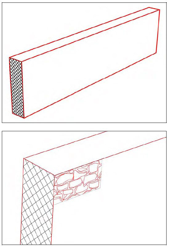
- for the structure: visualization of the edges of contact surfaces and their texture (Fig. 07)


4.2. A feature – higher level entity type
SUs are the result of the maximum atomization of the finding situation. In real practice, however, we most often move on a different terminological level. Even the field research itself carries a certain dose of the level of interpretation, which leads to the association of SUs into superior entities, colloquially “features“.
A feature is a category of terrain entity superior to SU (“usually associates more SUs”) and is defined on the basis of functional or temporal belonging of more SUs. These include, for example, “pit with filling” (= negative and deposit), “furnace” (pit as negative, dome as structure, filling as deposit) or “house” (meaningful set of column pits). Features can be hierarchized and encapsulated. The definition of a feature already carries a certain interpretive point of view.
- Features have independent record IDs (object 001 – nnn). It must be stated which SUs they consist of.
- The feature must be interpreted – which also justifies its definition.
- It is possible to create hierarchies of features and encapsulate them (e.g. stake pit – group of stake pits – stake house).
- The interpretation of features is based on a glossary created by an archaeologist / research technician according to the observed field entities.
- It follows from the above that in the case of handling with features in research, it is necessary to first define the glossary – categories of features and their possible encapsulation. Completing the records of features is associated with the definition of SUs, which consists of them.
- A specific type of feature is a grave. Although it is subject to the decomposition of the finding situation into SUs (negative = excavated grave pit; deposit = grave filling, etc.), it usually also contains human remains and has a clear function.
5. Arbitrary terrain entities – definition and documentation
Arbitrary field entities physically exist in a field situation, but unlike field stratification entities, their existence is not the result of deposition and post-deposition processes, but of the excavator’s decision. These are entities that define the scope of research and help cram the finding situation into comprehensible descriptive categories. Some of them are obligatory (they must appear in the finding situation and in the documentation), others are not.
5.1. Excavation polygon
Research polygons represent the basic spatial delimitation of field activity. The existence of polygons and their documentation is obligatory, i.e. any field activity must have defined research polygons.
1. polygons are defined even in the case of negative research results – ie even in the case that the remains of past human activities have not been proven in the research area. This rule is based on the principle that negative spatial information is as important as positive information.
2. The allocation of polygons depends on the criteria that must be justified. Most often:
- physical separations of polygons (“research probes are separated by an intact surface”)
- discovery procedure (“area numbers according to research discovery stages”)
- division according to the horizontal stratigraphy of the research (“wall dividing the overall situation into 2 areas”)
- etc…
3. there is a hierarchy of polygons within the research, which must be explicitly defined:
- first order polygons (most often “areas”)
- polygons II. order (“trenches”)
- polygons III. order (“squares”)
- etc…
The names of the categories (area, trench …) are not strictly defined and correspond to established practice rather than a clearly defined taxonomy. However, the definition of the polygon hierarchy is mandatory. Polygons of the same hierarchical level do not overlap spatially. Polygons of different hierarchical levels may overlap spatially and their hierarchical relationship must be stated.
In connection with the definition of polygons and their hierarchy, there is a record (list) of research polygons. This is a list of polygons with their hierarchical level. Research polygons must be focused or documented so that their spatial visualization is possible. Unlike the prevailing practice, where only the horizontal dimension of the polygon is documented, we consider the vertical disposition of the documentation to be no less important. The polygon is always documented in 3D projection (most often the top and bottom edge of the polygon).
5.2. Cut (section)
The cut is a planar vertical projection of the stratification of the finding situation. Unlike profile:
- the section is at least partially destructive – it irreversibly removes part of the stratification
- it is not possible to make an unlimited number of sections through a finding situation
- is a 2D area presentation of stratification
The section is not a mandatory part of field research, but in certain cases (e.g. narrow line excavations) the documentation is based exclusively on sections of a standard and acceptable form of research method.
If the conditions in the field research allow it, the so-called cumulative cuts have priority, the advantage of which lies in the full documentation of the SU even when cutting the stratified finding situation. To create a cumulative cut, a well-thought-out organization of the procedure and a certain manual skill are required.

Fig. 08. Principle of cumulative cut. According Ph. Barker, 1993.
Standard section documentation includes:
- list of field research sections – with reference to the cut SUs and with reference to the corresponding graphic documentation
- oblique field photograph of the finding situation with a section
- interpreted drawing presentation, which can take any of the forms of photogram or paper drawing
5.3. Profile
The profile is a line presentation of the SU surface. The prerequisite for the profile documentation is the correct identification of the SU surface and the choice of the profile course. Unlike the cut:
- is not a destructive documentation method profile
- allows to document only the surface of the current SU
- its measurement is in itself documentation. This does not apply in the case of a cut that is tied to a certain type of graphic presentation (drawing, section).
The profile is not an obligatory part of the documentation and serves mainly to refine the granulation of the graphic documentation of stratigraphy entities. Documentation of the profile, or profiles, can be a standard deployment method of documentation of all SUs (or all SUs of one type – typically negatives), or only selectively at SUs, where the field technician / documentary officer deems it necessary.
Usually, the course of the profile is documented using precise geodetic devices, although there are other, non-traditional methods. There is no separate record for the profiles, except for the measurement log. In the SU form it is necessary to check the box “profile measurement”.

Finds are movable artifacts recognized in the terrain situation and collected for further analysis. They are not an obligatory part of the research (“archaeologically negative research”). Principles of collecting findings:
- each finding must come from a defined SU. “Random” findings are not allowed
- it must be stated whether the findings are collected from the SU all (which could be identified), or whether they were only partially collected – a typical example of “sampling cuts “for fast dating
- finds are not collected during the cleaning of the finding situation, but only in the process of SU removal (i.e. no finds “at the SU interface”)
5.5. Samples
The sample is pars pro toto of physical SU (deposit, structure). It is taken for the purpose of more precise laboratory research and is not an obligatory part of the research. Principles:
- the sample must have a clearly defined relation to the entities of field stratification (e.g. belonging to SU)
- the purpose and type of samples must be defined
6. Documentation entities
Documentation entities are methods of documentation by which the terrain reality is described. As a rule, there are several ways of documenting one field entity and it is up to the conditions of research and erudition of the excavator which method to use.
Documentation during research usually exists in both digital and hardcopy form. Due to the fact that all documentation is digitized in further processing, direct acquisition in digital form takes precedence.
In principle, documentation by type is divided into:
- descriptive. Verbal description and categorization of findings and documentation.
- photographic/photogrammetric. Capturing finding situations with a true picture.
- interpreted drawing. Graphic presentation with a certain level of abstraction.
- geodetic. Spatial fixation of research entities and documentation entities.
6.1. Descriptive documentation
It contains lists of field and documentation entities, verbal descriptions of field entities and metadata about research (items marked with an asterisk “*” are mandatory for each field part of the project):
|
Descriptive documentation items |
Notes |
|---|---|
| SUs list* | basic records of all SUs defined by excavation (* = there has to be one SU on every excavation at least even if it is “archaelogicaly negative”) |
| SUs forms* | so-called “contexts desc.” – forms of description of individual SU, differing by type (deposit, negative, structure). (* = if there is at least one SU the descriptive form has to exist consequently) |
| features list | basic records of terrain features |
| features dictionary | definition of the types of features that have been defined in the field |
| burial form | grave description form |
| finds list | a list of findings as stratification entities, if they have been followed in the research |
| list of sacks with finds | aka “finds catalog” – list of findings from the contents of deposits, registration unit – “bag” |
| excavation polygons list* | basic evidence of research polygons (* = there has to be one polygon at least) |
| cuts list | basic records of possible cuts |
| sketches list | basic records of possible field sketches (including photo sketches) |
| drawings list | basic records of drawings (“millimeter papers”) |
| photographs list* | basic evidence of terrain photos (* = even negative excavation should be documented with photo) |
| photograms list | basic evidence of terrain photograms |
Descriptive documentation can appear in “hardcopy” – paper, or in digital form (field database), with the creation of digital form takes precedence.
6.2. Photo documentation
- It is an obligatory part of field research. Even if the research is archaeologically “negative”, the finding situation must be characterized by photography.
- Metadata. In the vast majority of cases, photos are taken on a digital camera. In addition to the photos themselves, EXIF data collection must also be set up.
- The field photographs must include at least one “general” (see below) photograph characterizing the overall situation and research environment
- Any technical photo (for a photogram) is usually supplemented by an oblique photograph, which adds “plasticity” to the documented situation, 3rd dimension. Additional graphic info is very important during processing for those who were not physically in the field.
- Photogrammetric documentation can be acquired only by those who control the photogrammetric processing of the collected data (= basic theory and work in specialized software).
- The author of the photos is responsible for their quality. As a rule, pictures in the field are taken redundantly, the selection of high-quality / deleting low-quality ones is fully in the competence of field workers – when submitting field data, photos must already be sorted, rotated to the correct position and named according to rules.
| Division according to further use | |
|---|---|
| technical photo | Photographs that can be used for a photogram – have at least an external orientation and parameters that allow them to be used for technical interpretive drawing. |
| non-technical photo | In general, documentary images without defined elements of internal and external orientation. |
| Division according to the orientation of the apparatus and composition | |
|---|---|
| oblique | oblique shot characterizing the finding situation, general information value |
| general | general scope of the whole research area; characterizes the environment and research conditions |
| detail | macrophotography of the finding situation (details of the funeral; exceptional finding, etc.) |
| vertical | orthogonal vertical photo to the finding situation |
| profile | orthogonal horizontal photo to the finding situation |
6.3. Drawing documentation
While photo documentation graphically faithfully characterizes the circumstances of the finding, drawing documentation is already a form of abstraction. The added value is its interpretation. The drawing documentation does not mean the complete CAD documentation that is created during the research processing (although real-time processing is not excluded), but directly the field drawing documentation:
- drawings – are an interpreted graphical presentation of a selected situation with mandatory localization (fixing points, fitting points) and to scale. The characterization or documentation entity is characterized by an agreed symbology. It is usually drawn on graph paper, but this is not a requirement.
- sketches – terrain sketch of finds and documentation entities (the sketches also include, for example, geodetic sketches) and serves for a quick orientation of the relations between them. Its symbology corresponds to the symbology of the drawing.
- photo sketches – are a special type of sketch, which is created by interpreting the background photo. The symbology used in creating the photo sketch corresponds to the symbology of the drawing. Photosketches have a specific relationship to photograms – each field photogram must have a corresponding photo sketch, which by default is created directly on the field by interpreting the finding situation. This requirement assumes adequate field equipment (PC, printer). Photo sketch does not have to be only the result of technical photography, it can be used as standard for the interpretation of e.g. oblique photography, aerial photography, etc., especially in more complicated situations that need to be deciphered.
6.4. Geodetic documentation
It is used for spatial fixation of field and documentation entities in the agreed coordinate system. The rules given in this manual are valid regardless of the geodetic technique used. Geodetic documentation is obligatory documentation, but it does not have to be performed by a total station. If a total station has been used, then a measurement protocol is a mandatory part of the documentation.
7. Mutual relations of field stratification entities, arbitrary field entities and documentation entities
The following tables show the obligatory relationship of individual entities of field research. These are relationships that are monitored and defined by default; another approach is substandard or abovestandard and must be justified. Entities marked with an asterisk (*) are an obligatory part of the field part of the project.
| Entity | If it exists, it must | Standard relationship |
|---|---|---|
| SU * |
|
|
| feature |
|
|
| grave |
|
|
| find |
|
|
| excavation polygon * |
|
|
| cut |
|
|
| profile |
|
|
| finds |
|
|
| sample |
|
|
| descriptive documentation * |
|
|
| photo documentation * |
|
|
| photogram |
|
|
| drawing |
|
|
| sketch * |
|
|
| photosketch |
|
|
| geodetic documentation * |
|
|
| geodetic protocol |
|
|